Getting started
Installing Bendyroad Development Studio
If you haven't installed yet, go to: Installation.
Starting the Development Studio
Double-click the desktop icon for the Bendyroad Devstudio.
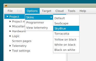
On first startup, you may find it a little too grayish, so you can choose a different skin:
Exploring the built-in example
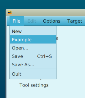
Under 'File', 'Example' is the classic "hello world" of firmware: the blinking LED.
Connecting a development board
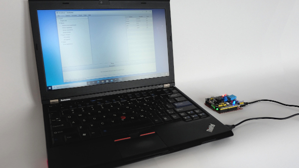
The example is for the Arduino Uno, but it is easily changed for other development boards. More on that later.
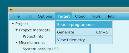
Go to 'Target', then 'Search programmer' to start the autoscan for a development board. Sometimes it can take a while to try a few ports before the board is found. (Only one connected board at the same time is supported)
Generating the firmware
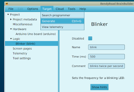
Go to 'Target', then 'Generate' to generate the example
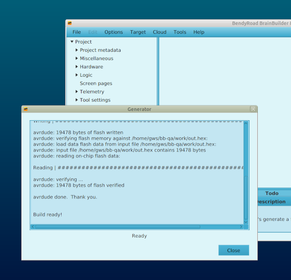
The first time you use Bendyroad Devstudio, a browser window will open to link your workstation.
Once the workstation is linked, the firmware is generated. Linking is a one-time thing, so the next times you generate firmware, it will be immediate.
After a few seconds the firmware is generated, flashed, and running on the development board.
Changing the example
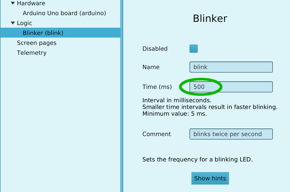
It's a good start to change the frequency of the 'blink', generate again, and see your change become effective quickly.
Saving the project file
It's convenient to create a folder to store your projects in. The folder is remembered for the next times you start Bendyroad Devstudio.
Starting a new project
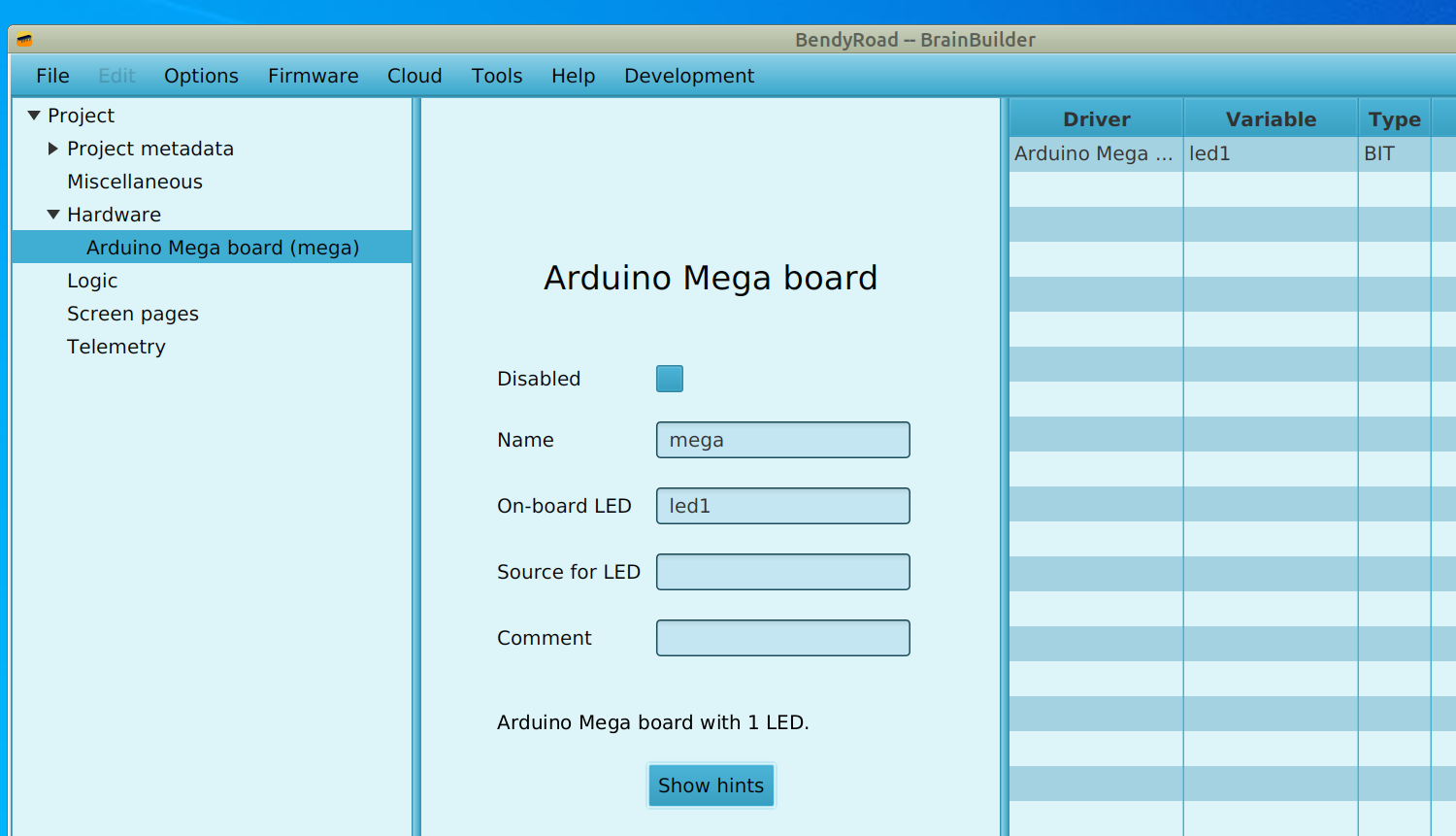
When starting a new project from scratch, always start by adding a development board (left-click on the 'Hardware' folder). For example an Arduino Mega board.
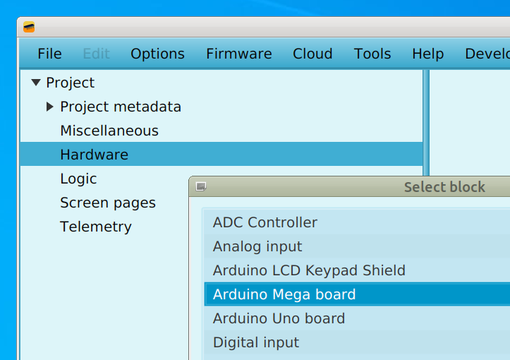
You can change the automatically assigned name to a name that is meaningful to you. The on-board LED is also assigned a default name that you can change. Note that in the list of variables on the left, 'led1' has been added as a variable of type 'bit'.
Adding more hardware
Display
If you have a Arduino Display shield or a generic LCD Display, you can add that too in the same way.
LEDs
Arduino Uno and Mega have an on-board LED that is already configured and available as 'led1'. Other LEDs you can add yourself.
Input
With analog and digital inputs, you can define which sensors or switches are connected to which pins.
Example: For using an analog temperature sensor on analog input pin 2, use an Analog Input block, name it 'temp' and specify the port as '2'.
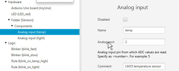
By clicking on any of the field descriptions, help texts are displayed, as in this example by clicking on 'Analog port'.
This automatically adds the variable temp. The list of variables on the right-hand side of the screen is updated with the new variable.
Output
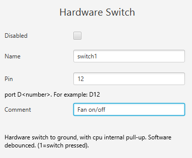
Example: A switch connected to Digital Output port 'D12'
Logic
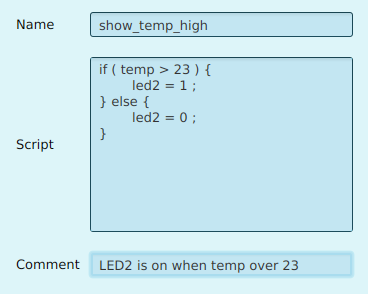
Rule blocks specify actions based on conditions. For example, to switch 'led2' on when 'temp' level over 23, and off if is below, add a rule like this:
if ( temp > 23 ) {
    led2 = 1;
} else {
    led2 = 0 ;
}
Global variables
Input blocks implicitly make variables available with the name of that block. For example 'Light'. But if it is easier to work with the inverse value, we can define a Global Variable with the name 'LightInverted' and type U16. Then we can add a Rule Block to set the variable 'LightInverted' to '1024 - Light'.
Output
If you have a LCD connected to your Arduino, add it as a hardware item:

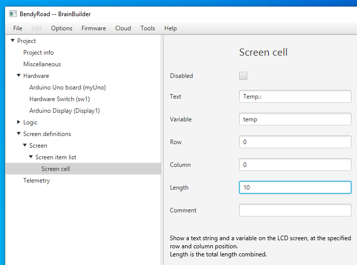
Next, add a 'Screen' under 'Screen Definitions'. This will create a 'Screen Item List', to which you can add 'Screen cells'.
A screen cell is the easiest way to display a text and a value together.
For example, to show the ADC value from the temperature sensor on the display, specify text 'Temp.: ', and a value from a temperature sensor (temp).
The Arduino display has two rows of 16 characters. Numbering starts at 0. An easy way to get the lay-out correct is to use grid paper.
You can enter project information on the Project Info page. There's room for a description and notes.
Reordering blocks
You can drag and drop blocks to reorder them, and organize them in folders, to logically group blocks together.